PATIENT POSITIONING AND IMMOBILIZATION IN RADIATION ONCOLOGY:
SOME CONSIDERATIONS
BY Gunilla C. Bentel, RN, RTT
Duke University Medical Center
Durham, North Durham
INTRODUCTION
Uncertainties associated with the delivery of a prescribed radiation treatment can be divided into two groups; uncertainties of dose (i.e., in homogeneities, dose calculations, variables in machine output and uncertainties in patient-beam geometry). Geometric uncertainties can be broadly divided into these inherent to mechanical inaccuracies in the treatment machine and those related to patient positioning which will be the focus of this report.
Geometric discrepancies caused by mechanical limitations/problems in the machine (beam angle indicators, beam-light coincidence, isocenter accuracy, etc.), in theory, can be eliminated by very rigorous testing and adjusting. In every day practice, however, we accept the fact that not all discrepancies can be corrected. It has been suggested, that displacements caused by mechanical machine inaccuracies, even when they are within the specified minimum requirements, can be <5mm while uncertainties of set-up and position of target volume due to patient or organ motion can cause errors of up to 8mm resulting in a combined uncertainty of <10mm.30 Variations in the day-to-day set-up are difficult to contend with because patients tend to move and there are inaccuracies aligning the treatment beam to the set-up marks. The American Association of Physicists in Medicine (AAPM) recommend <5mm spatial uncertainty.1 Several studies show that present practice does not meet these recommendations. Rabinowitz et al. showed in a study of 71 patients, that in 20% of set-ups, the spatial error was more than 10mm.22 Rosenthal et al. found a total uncertainty (random and systematic) of 0.7 cm in a retrospective review of 318 port films in 51 patients treated for head and neck malignancies using a bite block immobilization system.24 Byhardt et al. found, in a study of port films of 337 patients, that set-up errors >5mm occurred in 15% of the set-ups and in 10% of the set-ups, the error was >10mm.7
Although impossible to eliminate, spatial uncertainties caused by patient motion can be reduced by using an aggressive immobilization system and highly trained, compulsive technologists who take the time to carefully set up the treatment and pay meticulous attention to details. In this report, we will review the clinical implications of spatial inaccuracies and techniques to address the problem discussed.
I. GENERAL BACKGROUND
A. TARGET MARGINS AND FIELD DESIGN
In general, most treatment fields are designed to treat volume plus “a margin.” This margin is added to account for three factors. First, dose fall-off at the beam edge. Second, inaccuracies in defining the target volume, and third, inaccuracies in patient-beam set-up. The first factor is illustrated in Fig. 1. The edge of the beam-defining field light usually coincide with the 50% isodose level (Fig.1).
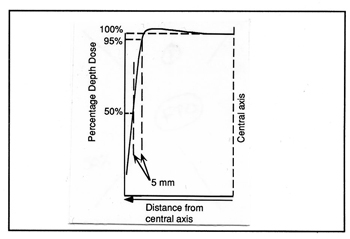
Fig. 1 The geometric edge of a treatment field is usually defined by the 50% isodose line, however, the dose is often prescribed to the 95% isodose line. The distance between the 50% and 95% isodose lines is, in most linear accelerators, approximately 5mm.
The distance from this geometric field margin to the 95% line varies from machine to machine but is often ~5mm on a linear accelerator. A 5mm margin for inaccuracies in target identification is a minimum value given the difficulties interpreting conventional diagnostic images and transferring this information to the simulator films. The third area of uncertainty lies in the reproductivity of the geometric patient – beam alignment and the probability of organ and patient motion. Many radiation oncologists add a modest 5mm margin to compensate for these uncertainties (Fig. 2). A combined margin of > 15mm is commonly added around the target volume. Under optimal circumstances, including the use of rigid patient immobilization, 3-D treatment planning systems, and conformal beam shaping, this margin may be sufficient. In the absence of these technologies, however, larger margins may be necessary.

Fig. 2 Margins are added around the target to compensate for uncertainties of defining the target volume, uncertainties in the set up accuracy and patient motion, and for penumbra of the beam.
When margins are added around the target to compensate for uncertainties, a large volume of normal tissue may be irradiated. A small reduction of the margin can have a significant effect on the volume of normal tissues that are exposed. The volume of normal but exposed tissue (outside the tumor) can be calculated for different target sizes and with different margins. The results of an idealized calculation are shown in Table 1 for a patient treated with a single field for a rectangular target volume irradiated with various size margins. The target is assumed to involve the entire 20 cm thickness of the patient. The target size shown in Table 1 represents the two dimensions perpendicular to the beam. As shown, a significant reduction in the volume of incidentally irradiated normal tissue can be recognized if the margin is reduced. For example, if the margins around a 10 x 10 cm target is reduced from 15 to 10 mm – a 5 mm reduction – in a 20 cm thick patient, the volume of tissue within the irradiated field is reduced from 2645 cm³ to 2420 cm³ – a reduction of 225 cm³. These numbers are only approximate and do not reflect the effect of the beam divergence or the use of multiple beams.
Since radiation induced complications do not occur in tissues that are not irradiated29, it is beneficial to minimize incidental irradiation of normal tissue. Keus et al.16 and Letschert et al, have shown that decreasing the volume of normal tissue within the irradiated field reduces the complication rate. Letschert et al.18 also found that by decreasing the volume of irradiated small bowel by a factor of 2, the total dose can be increased by 17% while the incidence of small bowel complications is unchanged. Reduction of the complication rate afforded by reducing the volume of irradiated normal tissue, may facilitate dose escalation and improved local tumor control rates. Goitein et al.13 has predicted, in an idealized mathematical model, that by decreasing the field margins by 5 mm in a supraglottic field, the total dose could be increased to where a 15% improvement in tumor control probability could be achieved without an increase in the normal tissue complication rate.
Table 1
Total volume of irradiated tissue versus tissue versus volume of normal tissue irradiated as a result of margins
(20 cm thick patient)
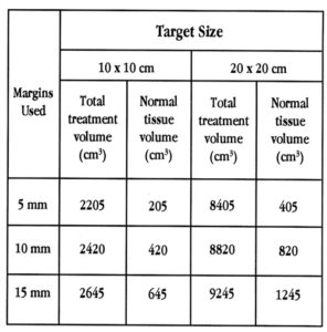
Table 1 The total volume of tissue and the volume of normal tissue within the geometric margins the treatment fields. A 10 x 10 x 20 cm target size is assumed. The volume of normal tissue is calculated by subtracting the target volume from the total treatment volume.
The change from colbalt-60 machines to linear accelerators, where the penumbra is much sharper and the dose is more uniform within the geometric edges of the field, has made it possible to reduce the tumor margins. The rapid dose fall-off near the edges, however makes even small beam displacements more critical. The introduction of customized beam-shaping blocks with divergent edges has further reduced the penumbra. It has also made it possible to shape the beam so that it more closely conforms to the shape of the tumor. Prior to custom shielding capabilities, tumor margins were sometimes excessive because blocks were generally limited to standard shapes. Areas that previously could not have been shielded can now be blocked, thus reducing the volume of normal tissue irradiated.
Advances in 3-D diagnostic imaging, particularly CT and MRI, have improved the accuracy of target volume localization and may facilitate the use of smaller margins. It is important, however, to recognize that these diagnostic modalities may not be ideal. If the extent of tumor involvement is underestimated, marginal misses may occur. The treatment fields can also be designed with more confidence when three-dimensional treatment planning systems such as the Virtual Simulator*26 is used. This system allows the user to view the tumor from any arbitrary direction and to determine the “optimal” beam orientation. The shape of the treatment field can be designed to closely resemble the shape of the target in the beam’s-eye view, thus limiting the volume of normal tissue within the radiation beam. The ability to limit the volume of normal tissue in some instances may allow higher doses to be delivered in the target, thus increasing the probability of local tumor control. 27,28 However, precision and effective immobilization techniques are essential.
B. THE EFFECT OF MISALIGNMENTS
An important area requiring precision is the geometric alignment of the patient on a day-to-day basis and the accuracy with which each machine parameter is set by the technologists. To miss part of a tumor once or twice during a treatment course could markedly reduce the dose to that segment of the tumor depending on the total number of fractions. Similarly, inadvertent movement of a critical structure into the radiation beam during a few treatments might cause severe morbidity. Failure to deliver the pre-scribed dose may be prevented by the use of effective patient immobilization. The development of tools and techniques with the goal of positioning and immobilizing the patient, however, has not kept abreast with the development of modern treatment techniques. The interest in treatment reproducibility has primarily been in the head and neck area and several immobilization devices for this purpose have been described.2,11,12,14,15,19,32,33
Some older studies of mantle fields suggest that inaccuracies in patient set up may impact on local tumor control. Maruyama et al. reported a 33% recurrence rate in sites adjacent to the blocked areas in patients with Hodgkin’s disease involving the mediastinum.21 Rubin et al. a 12% marginal recurrence rate in patients treated for Hodgkin’s disease.25 Marks and Haus presented data from a retrospective review of portal films of 902 set-ups on 99 patients with Hodgkin’s disease and malignant lymphoma and found that in 36% of the set-ups, the position of the shielding blocks were not duplicated as planned.20 In 10 of 99 patients the disease was not controlled locally. Two of these failures were at the margins of the fields and were shown by portal films to be correlated with positioning errors leading to reduced dose at the sites of recurrence. More recently, Kinzie et al. reported in a Patterns of Care Study, on the consequences of field misalignments in 155 patients treated for Hodgkin’s disease.17 They found that with inadequate tumor margins, the in-field and marginal recurrence rate increased from 7% to 33%. From these studies one might conclude that errors in treatment delivery, including patient positioning errors, may be a significant cause of marginal recurrence. It is probably safe to assume that, in these fairly old studies, patient immobilization and target identification were not as rigorous as they are today and that marginal recurrence rates therefore are likely to be lower today.
Goitein et al. using a model, studied the effect of under dosage at the perimeter of the treatment field caused by random immobilization errors.13 They found that as much as 12% improvement of tumor control probability could be achieved by good immobilization techniques in a supraglottic field. The authors conclude that good immobilization as a means of improving tumor control in supraglottic carcinoma is important. Recognition of these spatial uncertainties is one of the reasons why margins are placed around the tumor volume, as described in the previous section.
The need for effective patient immobilization to reduce misalignments has been recognized by many radiation therapy centers as evidenced by the increasing number of studies reporting on immobilization techniques and the ability to reproduce the planned treatment.6,8,9,10,23,24,31,34
II. PATIENT REPOSITIONING
In all of radiation therapy, it is necessary to establish the precise position of the target in three dimensions with respect to some visible external marks. A realignment system, used to aid in the repositioning of the patient, is usually mounted in each treatment room. This system consists of three laser lines projected such that each line coincides with one of the three axes and all lines coincide at the isocenter of the particular machine in the room. One line is projected from the ceiling and coincides with the in-out motion of the couch (sagittal plane in the patient). Two opposed crosshairs are projected from the walls of the room; one coincides with the up-down motion of the couch (transverse plane in the patient), and the other with the right-left motion of the couch (cornal plane in the patient). It is important to recognize that the laser alignment system is fixed with respect to the treatment machine and that the patient must be realigned with these lines for each treatment session. The alignment lines, marked on the patient’s skin and/or on an immobilization device during the target localization procedure, are used to realign the patient with an identical alignment system in the treatment room. In most treatments it is desirable to place the isocenter of the therapy machine in the center of the target volume and then, through changes on the collimator, couch, and gantry angles, direct the beam at the target. If the marks and the target do not move with respect to one another, realigning the patient with these lines will insure that the target is repositioned with respect to the radiation beam. It is not sufficient to align the patient with just three points. Rather severe errors in the treatment can result if only the isocenter is realigned, particularly when large fields are used (Fig. 3).
Practical the entire body of the patient must be aligned with the alignment lines in order to assure that the treatment field covers the intended volume. This leads to other considerations such as the precise coincidence of the entire alignment line with the axes of the motions of the couch. The sagittal alignment line must, for example, follow precisely the in-out motion of the couch. It also becomes essential to immobilize almost the entire patient even when just the breast or the prostate is treated. Alignment marks can then be made on the immobilization devise as well as on the skin, and, as long as the patient is repositioned correctly in the device, the entire treatment field will be repositioned correctly.

Fig. 3 A treatment field, correctly set up at the isocenter, may still be misaligned if the patient is not aligned with the entire length of the alingment lines. The error is largest when farthest from the isocenter (A & B).
A. REALIGNMENT MARKS
Alignment marks made on the patient’s skin are often unreliable as soft tissue tends to move over underlying deeper organs. If we could for just a moment think of the patient as a mannequin where the surface is rigid we would realize that marks made on the surface will always remain in the same fixed place with respect to deeper points. In a human, on the other hand, the skin can be moved over underlying bone anatomy. For example, a mark made on the back of the hand when the fingers are extended will move with respect to the underlying bones when a fist is made. Skin marks made on breast tissue can easily move several centimeters with respect to the chestwall, the suprasternal notch, or other rigid points on the patient’s chest. Likewise, set-up marks made on the skin in the pelvis of an obese patient will move with respect to underlying bony anatomy. The distance by which these marks travel depends on the thickness of the soft tissue layer between the skin and the rigid bones. Skin marks are most satisfactory when the target is superficial, for example, when a palpable lymph node is treated. In most radiation treatments, however, the beam is directed at a deep-laying tumor. In these situations, skin marks made during the treatment simulation procedure are not reliable. Set-up marks made on the immobilization device is more reliable than skin marks as long as the patient is repositioned correctly in the device. Marking the alignment lines on an immobilization device also eliminates the risks of the marks washing or wearing off and prevent migration because they do not need to be reinforced.
III. PATIENT IMMOBILIZATION
The need for effective patient immobilization has increased as technologies developed during recent years have improved the ability to identify the target and to design the treatment fields to conform to the target. One of the most important aspects of immobilization is to position the patient in a practical position. The patient’s position during treatment must be decided with consideration given to the anticipated beam arrangement. The treatment planning team must know what type of beam arrangement is anticipated prior to making the immobilization device. It is also important to place the patient in a comfortable yet reproducible position. A patient who is uncomfortable will have difficulty in maintaining the position even for short periods of time and without proper supports the position may be difficult to reproduce on a day-to-day basis.
Another essential consideration when immobilizing a patient is the need to fix at least two points with respect to one another, one on each side of the intended treatment field. For example, when the para-aortic nodes are treated, the chest and the hips need to be fixed to prevent curvature of the spine and the trunk of the body. When a soft tissue sarcoma in the arm is treated, the chest, arm, and hand need to be fixed with respect to one another. A rotation of the hand can change the relative position of the muscles in the arm thus, possibly moving the tumor out of the radiation beam. The ability to immobilize two bony points with respect to one another in a rigid fashion is related to the thickness of the soft tissue which lies between the bony prominence and the immobilization device. If the immobilization device is in direct contact with the skin surface, for example in the hips, the patient’s bony pelvis can still be rotated. In the head and neck area, where bony prominences are generous and the thickness of soft tissue is small, immobilization can be very effective. However, if only the tip of the nose, which consists of cartilage and soft tissue, is a very flexible prominence. Immobilization of portions of the body which contain fewer bony anchor points are most difficult and may therefore require that the immobilization device includes large sections of the body. Immobilization of the pelvis, for example, requires that the immobilization mold extend from the chest to below the feet and that it fits tightly underneath and on each side of the patient. Changes in the position of the feet also changes the appearance of the bony pelvis on a radiograph and could lead to inappropriate field shifts when port films are reviewed. A thin patient would be very uncomfortable in a tight-fitting mold if the bony prominence did not fit precisely into the grooves formed when the mold was made while in an obese patient it might be more difficult to detect a positioning problem.
The difficult task of immobilizing and repositioning the patient has been made possible through the ALPHA CRADLE®* brand Patient Repositioning System. ALPHA CRADLES® consists of a series of Styrofoam®** forms that roughly match a patient’s anatomy. Two bottles of foaming agents are mixed and the content is poured inside the form. With a large polyvinyl bag covering the form, the patient is placed in the desired treatment position in the form. The foam expands and fills the space between the patient’s skin surface and the Styrofoam® form, thus, forming a mold under and on the sides of the patient. The height of the sides of the mold can be monitored by the user by extending the bag up to the sides to desired height. It is generally a good practice to make the sides at least 6” high and in very close contact with the patient’s skin to form a tight “cradle” (Fig. 4). This can be accomplished by either pushing the foam while it is soft toward the patient’s sides or by stretching masking tape across the ALPHA CRADLE® to force the foam toward the patient until the mold is hard.
* Registered by Smithers Medical Products, Inc.
** Registered by Dow Chemical

Fig. 4 An effective Alpha Cradle® form must fit tightly to the patient’s skin surface (arrows) and “cradle” the patient.
ALPHA CRADLES® constitute and excellent immobilization system which can be adapted to any part of the patient’s anatomy. In the following paragraphs, the use of ALPHA CRADLE® in the Department of Radiation Oncology at Duke University Medical Center is briefly described. Detailed descriptions can be found elsewhere.
A. HEAD AND NECK IMMOBILIZATION
Immobilization techniques of patients treated for malignancies in the head and neck region are probably the most advanced and have been tested more than any other system. The need for rigid head and neck immobilization is prompted by the often very narrow margins between tumors and critical organs such as the lens of the eye, the brain stem, optic chiasm, and the cervical spinal cord. We have elected to use customized supports that fit tightly to the back of the patient’s head, neck, and shoulders. Alpha Cradle® brand foaming agents* poured into a plastic bag placed under the head and shoulders expands and fill the empty space behind the patient. This support offers a comfortable cup into which the patient’s head rests. When this support is hardened, a thermoplastic sheet, which is soften in hot water, is draped over the patient’s face from the middle of the forehead to below the chin. This thermoplastic sheet is attached to a base plate which in turn is fastened to the treatment couch. The thermoplastic sheet will become firm in approximately 5 minutes. Efforts are made to make a tight fit over the bridge of the nose where there is only a thin layer of soft tissue between the skin and the bone, thus, it is an excellent anchor point.
This head immobilization mask is very tight and must be made with the patient undressed from the waist up. If attempts are made to replace the mask on the patient while he/she is wearing a shirt other than when the mask was made, the patient will complain because it is too tight. In this system, the mask secures the head to the base plate and the base plate is fastened to the treatment couch preventing any skewing or rotation of the head. A unique benefit of many head and neck immobilization devices is that set-up marks can be made on the device (a mask or cast), which obviates the need for unsightly marks on the patient’s face.
*Registered by Smithers Medical Products, Inc.
** Registered by Velcro USA
*** Trademark of Smithers Medical Products, Inc.
B. BREAST IMMOBILIZATION
Patients treated for malignancies in the breast are probably the most difficult to reposition and therefore require an aggressive immobilization system. In our practice, these patients are immobilized in an ALPHA CRADLE® form which extends from above the head to just below the knees. The arm on the involved side is raised and a handle onto which the patients can hold on during the treatment is built into the ALPHA CRADLE® form along with a support the arm³. The set-up marks are made on the ALPHA CRADLE® form as far from the isocenter as possible, as well as on the patient’s skin surface. Aligning two points separated by a long distance improves the accuracy of the set-up (Fig. 5). The sagittal alignment line is marked on the ALPHA CRADLE® form above the patient’s head and between the knees as well as on the chest. The transverse line is marked on each side of the ALPHA CRADLE® form and on the chest while the cornal or horizontal lines are marked on the patient or the ALPHA CRADLE® form depending on the height above the table top. Because of the complex angles used in the treatment of breast patients, the alignment lines are marked with the patient in the neutral couch position. If there are discrepancies in alignment during the set-up the marks on the ALPHA CRADLE® form are considered more reliable than the skin marks.
Patients with large or flaccid breasts often require repositioning of the breast on the chest. A Bravelle™***, single breast immobilization system, is used for this purpose. The Bravelle™ consists of a polyvinyl tube formed to a ring and placed around the base of the breast. The ring is the fastened to a Velcro®** band placed around the patient’s chest. The breast is fixed in the desired position by tightening the Velcro® band.5
C. IMMOBILIZATION OF PATIENTS WITH HODGKIN’S DISEASE
Patients treated for Hodgkin’s disease are immobilized in an ALPHA CRADLE® form which extends form above the head to below the knees. Handles are built into the superior aspect of the device for the patient to hold onto during the treatment.4 These handles help in reproducing the arm elevation and also prevent the patient from having to strain to maintain the elevated arm position. Alignment marks are made both on the ALPHA CRADLE® form and on the patient’s skin surface. The sagittal alignment line is marked on the patient’s chest and abdomen and on the ALPHA CRADLE® form above the head and between the knees. The transverse line is marked on the chest or abdomen, depending on whether the mantle or the para-aortic fields are treated, and on the ALPHA CRADLE® form. The coronal or horizontal lines are marked on the patient or on the ALPHA CRADLE® form depending on the height above the table top.
D. THORACIC IMMOBILIZATION
In our clinic, patients with thoracic malignancies are immobilized only if they are treated with curative intent or are candidates for three-dimensional treatment planning. ALPHA CRADLE® forms extending from above the head to the knees are then used. Alignment marks are made on both the patient and on the ALPHA CRADLE® form as described for patients treated for Hodgkin’s disease.
E. PELVIC IMMOBILIZATION
Patients treated for prostate malignancies are immobilized in an ALPHA CRADLE® extending form the mid-chest to below the feet.6 By including the feet in the mold, variation in the foot position which would also change the orientation of the bony pelvis, is prevented. This mold extends approximately 6” above the couch top on each side of the patient. Set-up marks are made on the ALPHA CRADLE® form as well as on the patient’s skin. The sagittal alignment line is marked on the patient’s skin and on the ALPHA CRADLE® form between the legs from the thighs to the feet. Two transverse alignment lines are marked on the patient and on the ALPHA CRADLE® form; one on the pelvis and one just below the knees. The mark below the knees, where there is a very thin layer of soft tissue over the tibia, is to verify that the patient is repositioned correctly in the cephalad direction. The coronal or horizontal lines are marked only on the ALPHA CRADLE® form. If there is a discrepancy between the marks on the patient’s skin and on the ALPHA CRADLE® form at any time during the set-up, the technologists use the marks on the ALPHA CRADLE® form. These marks do not move with respect to deep rigid anatomy and with the patient repositioned correctly in the ALPHA CRADLE® form the treatment geometry is reproduced.
1. “BELLY BOARD”
In a large number of patients it is desirable to move as much as possible of the small bowel out of the treatment field. The patients are positioned in the prone position hoping that gravity will cause the small bowel to move anteriorly. An ALPHA CRADLE® form is built which has either an opening under the pelvis to remove and resistance for the bowel, or with a compression roll under the lower pelvis to force the small bowel superiorly. The reproducibility of such set-up can be quite difficult, particularly in patients who find it difficult to assume the prone position. Figure 5 illustrates a patient where the small bowel was outline on a series of CT images using a three-dimensional treatment planning system. The treatment field was angled and designed to avoid the small bowel. Several days later, the planned treatment fields were simulated. The patient was given oral small-bowel contrast and radiographs of the planned fields were taken to verify the exclusion of the small bowel. Figure 5 shows a treatment field template generated from the 3-D treatment planning system superimposed on the simulation radiograph. Considering the motion of the small bowel, the reproducibility of this complex field is excellent. Precise repositioning of this very difficult elderly, handicapped patient would not have been possible without the ALPHA CRADLE® form.
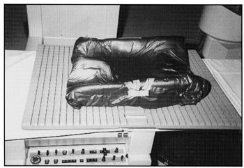
Fig. 5 A template of the treatment field produced from the 3-D planning system and superimposed on the simulation radiograph. Small bowel contrast and bony landmarks confirm the excellent patient repositioning in a prone “belly Board” Alpha Cradle®.
F. IMMOBILIZATION OF EXTREMITIES
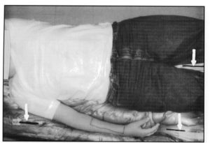
In our clinic, ALPHA CRADLE® forms are used for patients treated for lesions in an extremity. In these patients it is critical for the treatment planning team to know the anticipated beam arrangement prior to designing the first immobilization device. The position of these patients is often complicated by efforts to avoid irradiating unnecessary volumes of normal tissue. When one lower extremity is treated, for example, it is crucial to move the opposite lower extremity out of the path of the beam (Fig. 6). ALPHA CRADLE® Forms are built to immobilize the patient from the waist to below the feet. When one upper extremity is treated, the entire chest and arm is immobilized in an ALPHA CRADLE® form (Fig. 7).
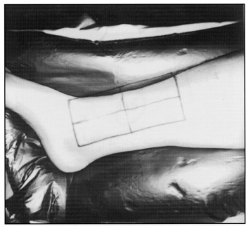
Fig. 6 Lower extremities immobilized and fixed with respect to the pelvis in a patient with a tumor in the right leg. The legs are separated to keep the unaffected leg away from the path of the beam in anticipation of oblique fields.
Fig. 7 Upper extremity immobilized and fixed with respect to the thorax in a patient with a tumor in the medial aspect of the lower arm. Repositioning of the fingers into grooves made in the mold prevents rotation of the hand. Alignment marks are made on the ALPHA CRADLE® form above the head (not shown) and between the thighs.
G. CRANIO-SPINAL IMMOBILIZATION
For both adult and pediatric patients treated to the entire Central Nervous System (CNS), a prone head Styrofoam® form is used in conjunction with a body form. Foaming agents are used around the face and the body. After the ALPHA CRADLE® form has hardened, the patient is asked to raise the head and a thermoplastic sheet is stretched across the facial portion of the head support. When the patient’s head is repositioned, the soften thermoplastic sheet is gently presses against the patient’s face, particularly over the bridge of the nose to provide a tight fit. Openings are eventually made on each side of both the thermoplastic mask and the ALPHA CRADLE® form to allow the eyes to be visualized during the set-up.
The CNS ALPHA CRADLE® form has replaced our total body plaster casts which were heavy to handle and usually required two days to dry. The ALPHA CRADLE® form is made in less than 30 minutes and the simulation procedure can begin immediately. This is a very important aspect because these patients often need to start the treatment with short notice. We also find that it is easier for the patients to enter and exit the ALPHA CRADLE® form than the plaster cast. The patient for whom we made this ALPHA CRADLE® form was a paralyzed youth who it was felt, would not have been able to get into the plaster cast without a lot of help. The set-up reproducibility, confirmed by weekly port films, was excellent.
H. MISCELLANEOUS
ALPHA CRADLE® BRAND patient Repositioning Systems are used in our department for many other situations. For example, patients that are treated in decubitus position, patients that appear to be difficult to reposition, obese patients, and pediatric patients. One ALPHA CRADLE® form was recently made for an elderly deaf and mute patient who was worried about falling off the narrow treatment couch. We also use ALPHA CRADLE® forms for positioning patients receiving hyperthermia treatment and for companion animals (cats and dogs) treated in our department for spontaneously occurring tumors.
IV. RESULTS
We feel that it is crucial to routinely review port films to evaluate performance and to screen for any systematic errors. During the efforts to improve our immobilization techniques, a retrospective review of port films was made to determine the frequency and magnitude of patient-beam misalignment. The results of the port film review of patients treated with newer immobilization devices were compared with the findings in a similar group of patients treated using an earlier version of the immobilization device. Patients treated for prostate carcinoma had previously not been immobilized, therefore, the results from the port film review of the immobilized patients were compared with a similar group of patients without any immobilization device. In all of the disease sites for which ALPHA CRADLE® Patient Repositioning Systems are used, we have improved the patient-beam alignment rates as shown in Table 2. Despite these improvements in patient-beam alignment, we will continue to perform routine retrospective port film reviews and to seek superior methods of patient immobilization.
Table 2
Frequency of treatment field misalignments determined on retrospective port film review for various treatment sites
* Port film review included only routine port films
** Current immobilization is compared with no immobilization
+ Current immobilization is compared with that of using a short Alpha Cradle® form
~ Current immobilization is compared with that of using standard head supports and strips of casting material
V. SUMMARY
In recent years, a number of technologies, which are invaluable in defining the target volume and in determining the optimal treatment plan, have been introduced. The patient’s anatomy can now be observed in great detail from any direction on a computer monitor by “peeling away” the skin and other tissues and organs. A treatment plan can be designed in such a way that the resulting dose distribution conforms closely to the target volume. The increased confidence with which the treatment now can be delivered, along with sharply defined penumbra of linear accelerator beams and the capability to customize the field shape to the target, has lead to the use of smaller tumor margins, thus the volume of normal tissues within the irradiated field is reduced. The reduction of the normal tissue volume within the irradiated field may reduce morbidity and facilitate the delivery of higher doses and hopefully improve cure rates. This approach requires accurate and reproducible patient immobilization.
The precision with which the treatment now can be planned and delivered has reached new heights, however, the accurate delivery of the treatment depends on the meticulous attention to details by everyone involved. The role of the technologists, who actually deliver the treatment, can never be sufficiently emphasized. However, without effective patient immobilization, the ability to carry out the treatment as planned is compromised.
Retrospective review of portal films of patients with various curable diseases should be carried out by every radiation therapy department on a routine basis to determine the frequency and magnitude of treatment field misalignment. The results of such reviews will demonstrate any need for improvement and it could also reveal systematic errors in the treatment delivery. The day-to-day set-up variability can be improved with the use of an aggressive immobilization system. This is not to say that an aggressive immobilization system will eliminate all day-to-day set-up variations, but it will certainly reduce the errors in patient-beam misalignment.