IMMOBILIZATION TECHNIQUES AND DOSIMETRIC ASPECTS FOR PITUITARY TUMORS
Mona K. Weller, RTT, BS, CMD
Patricia L. Muller, RTT, BS
Stanley Sugai, RTT, CMD
Jo Levenick, RTT
Hahnemann University
Philadelphia, Pennsylvania
INTRODUCTION
Twelve percent of intercranial tumors arise in the pituitary gland.1 The sella turcica houses the most common adult tumors-pituitary adenomas. Pituitary insufficiency and hypersecretion may occur if pituitary gland, the stalk, or the hypothalamus is compressed by the tumor. As these tumors enlarge upward they compress the under surface of the optic chiasm causing visual field defects.
Formal endocrine evaluation is important in patients with pituitary tumors. An ophthalmic evaluation should be included to establish tumor involvement. The extent of pituitary dysfunction should be evaluated prior to the initiation of any treatment.
Diagnostic studies are essential for planning and evaluating the mode of treatment. Computerized tomography (CT) with contrast of the brain is one informative test for location and nature of the tumor. Magnetic Resonance Imaging (MRI) may provide valuable information in defining the anatomical extent of disease. CT and MRI scans can be utilized for radiation therapy treatment planning.
Treatment options for pituitary adenomas are drugs, surgery, and/or radiation therapy. This paper will deal with radiation therapy and the implementation of treatment.
Through the mid-1980’s, pituitary were treated at Mallinckrodt Institute of Radiology with parallel opposed lateral portals², utilizing an 18 MV photon beam. Subsequently an isocentric three-field technique, AP coronal and opposed laterals, has been used to provide a more uniform dose distribution and spare the temporal lobes. With the use of the three-field technique or a rotation (flying wedge) technique, positioning is very critical, creating a need for a more stable form of immobilization.
IMMOBILIZATION TECHNIQUES
BITE BLOCK
The parallel opposed lateral technique utilized a bite-block immobilization system. With this system, the patient lies supine with their head on a positioning form and the form is held in place by Lucite base plate. This Lucite base plate is cut-out in the middle to accommodate the positioning form and is centered on the couch by means of lateral bars. Softened dental clay is molded onto a Y-shaped fork and the fork is then attached to a scaled horizontal bar which in turn is mounted on a scaled vertical bar. This vertical bar is attached to the head of the table and the Lucite base abuts the bar. The patient makes a dental impression on the softened dental clay and the scale readings are recorded. This system ensures reproducible placement of the patient by setting the same scale readings daily and the positioning form is in a fixed position. This technique requires significant patient cooperation since the patient must maintain the fixed head position by biting on the dental clay.
THERMAL PLASTICS
The three-field technique requires the patient to flex the chin, with the orbital metal line (ML) perpendicular to the table top, to avoid treatment of the eyes from the AP coronal portal. This position is very difficult for the patient to maintain without assistance. The immobilization method we initially selected utilized a Styrofoam block and wedges under a head-positioning form with a thermal plastic mask clamped to a Lucite base. Clinical experience proved this immobilization technique to be inadequate, as the head was elevated off the Lucite base causing the over-sized thermal plastic mask to be too flexible. To solve this problem, additional thermal plastic material would have been needed over the coronal and lateral portal area to minimize head rotation and increase mask rigidity. This would not have been acceptable due to the loss of skin sparing.
ALPHA CRADLE® BRAND PATIENT REPOSITIONING SYSTEM
A more comprehensive solution for immobilization has been found in the use of a polyurethane foam form (ALPHA CRADLE® brand form)³ utilizing the Smithers Medical Products, Inc., ADULT HEAD FORM (HFI)³. The HFI kit consists of a Styrofoam® mold, two Styrofoam® wedges, foaming agents 1 & 2, plastic sheeting, gloves and cap. Prior to simulation, the wedges included with the kit are taped into the head form. The plastic sheeting is taped to the bottom of the form on both sides and the inferior edge, leaving the superior edge open.
Another immobilization technique utilizes a slant board, Smithers Medical Products, Inc. ACMM foaming agents³ and a fabricated Styrofoam® head form developed in Honolulu, Hawaii. The immobilization form is molded by using a Styrofoam® head former, a heavy duty plastic bag, and foaming agents 1 & 2. The Styrofoam® head former consist of two 12” x 12” high density Styrofoam® blocks cut in the shape of a head, then cut in half, and taped together so they are 6” high.
SIMULATION PROCEDURE
Three-field Technique: Simulation of the three-field technique begins with the patient supine. The head is placed in the Styrofoam® mold with the chin flexed. With the gantry horizontal, fluoroscopy is used to verify proper patient position. If increased head flexion is required, additional Styrofoam® wedges are placed under the Styrofoam® mold. Once proper positioning is achieved, laser points are marked on the patient’s lateral and anterior coronal surfaces using ceiling and lateral lasers. The additional wedges are removed. Foaming agents 1 & 2 are mixed according to instructions and poured into the form which is flat on the table. It is important that the form be flat to prevent the foam from pooling around the shoulders and base of the skull causing possible spillage and/or lack of immobilization around the head. The patient is then repositioned into the form, and aligned with the anterior coronal and lateral lasers. While the foam hardens around the patient’s head, care must be taken to maintain the patient’s position. To restrict excessive foaming in the area of the lateral portals, simply press the foam down. The foaming and hardening process is completed within 15 minutes. After the patient is removed from the form the additional Styrofoam® wedges are attached to the previously marked position.
The patient is then repositioned and the simulation continues, verifying and taking simulation films of the AP coronal and opposed lateral portals. After the treatment portals are determined, filmed and marked the central axis of each portal is tattooed. Optical distance indicator (ODI) readings are taken for each portal. Patient contours and diameters are taken to aid in the treatment planning process.
Rotation Technique: The simulation for the rotation procedure begins with the patient supine on the slant board with a 15” rise, which eliminates 15° of the patient’s neck flexion. This enables the patient to comfortably hold the head position. With the use of fluoroscopy the proper head position is determined. Once this is achieved the lateral and AP coronal lasers are marked on the patient’s skin surface. The patient then sits up and the bottom of the plastic bag is taped to the slant board at the level of the patient’s shoulders. After following the mixing procedure for the foaming agents, they are poured in to the plastic bag. The open end of the bag is taped closed except for a small opening in one corner to allow the excess air to escape. The patient is placed onto the slant board and into the three point set-up and the ALPHA CRADLE® foam is allowed to mold around the patient’s head. It is helpful if a small amount of foam flows over the superior edge of the slant board to form an edge. This edge is useful in positioning the form in the same location every day.
DOSE DISTRIBUTIONS
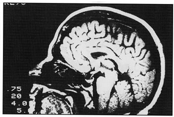
CT of MRI scans are useful for treatment planning purposes (Fig. 1, 2, 3).

Fig. 1 Sagittal MRI scan.

Fig. 2 Transverse MRI scan.

Fig. 3 Coronal MRI scan.
Pertinent internal structures such as target volume, temporal lobes, and brainstem must be accurately entered relative to the external contour in order to adequately evaluate the treatment technique.
Evaluation of the isodose distributions associated with the different treatment techniques were made based on the maximum and minimum doses to these internal structures. CT and /or MRI scans used to evaluate the tumor are not usually done with the patient in the treatment position therefore it is beneficial to obtain a treatment planning CT (1-4 cuts) using the ALPHA CRADLE® immobilization device to reproduce patient position. The use of a CT with the patient in the treatment position will confirm that the radiation field is encompassing the target volume. The isodose distributions for the treatment techniques discussed have been normalized to give 100% dose at the isocenter. The isodose calculations for all the techniques utilized a 6 cm x 6 cm field defined at 100 cm SAD.
The parallel opposed lateral field technique isodose distributions were calculated using 18 MV photons and equal beam weighting. The 100% isodose does not cover the target volume, the 90% isodose covers a large portion of the temporal lobes and the 50% isodose reaches the surface (Fig. 4). The increased surface dose will cause hair loss. It is also important to realize that the maximum tumor dose is 100.2% and the minimum tumor dose is 97% of the prescribed dose.

Fig. 4 Isodoses for parallel opposed laterals 18 MV, 6 cm x 6 cm, 100 cm SAD.
The isodose distribution of the three-field technique was calculated with 6MV photons using 45° wedges on the lateral portals. The beam weighting is 44% from the AP coronal portal and 28% from each lateral portal. The target volume is covered by the 100% isodose line with the 50% isodose line covering the temporal region (Fig. 5). The maximum dose to the target volume is 100.8% and the minimum is 100%.

Fig. 5 Isodoses for 3-field technique, 6 MV, 6 cm x 6 cm, 100 cm SAD, 45° wedges on lateral portals.
The same technique calculated with 18MV photons shows the 100% isodose line encompassing approximately one-half of the target volume, the 99% isodose covering the target volume and the 50% isodose line covers a large portion of temporal lobes (Fig 6).

Fig. 6 Isodoses for 3-field technique, 18 MV, 6 cm x 6 cm, 100 cm SAD, 45° wedges on lateral portals.
The maximum target dose is 100.2% and the minimum is 99%. The decrease in surface dose will minimize patient hair loss and the temporal lobe dose had decreased from 90% with the parallel opposed lateral field technique to 50%. The isodose distribution for the rotation technique was calculated with 18MV photons, a 180° arc and a 45° wedge that is rotated at the top of the arc. The beam weighting is equal. The 100% isodose does not cover the target volume, 98% covers the target volume and the 50% isodose line covers approximately one-half of temporal lobes (Fig. 7) The maximum dose is 100.3% and minimum dose is 99%.
CONCLUSIONS
When treating with the lateral technique the biteblock system is an adequate method of immobilization for cooperative patients. This system however is inadequate for uncooperative patients or when a treatment technique requires increased head flexion. With the rotation or three-field technique the biteblock system cannot be used as the scaled horizontal bar will obstruct the AP treatment portal.

Fig. 7 Isodoses for rotation technique, 18 MV, 6 cm x 6 cm, 100 cm SAD, 45° wedge.
The thermal plastic mask solved these problems but was not rigid enough to prevent patient motion. Implementing the ALPHA CRADLE® form minimizes patient movement and allows the treatment technique of choice.
Dosimetrically the three-field and rotation technique show an improvement over the lateral technique. This is demonstrated by the decreased dose to the temporal lobes by approximately 40% when comparing the three-field plan to the lateral plan. When treating with the rotation (flying wedges) technique the treatment plan shows an even greater reduction in dose to the temporal lobes. The low surface dose when using an 18 MV photon beam minimizes the patients hair loss.
The four P’s in treatment delivery of radiation are very important:
1) The precision of daily dose delivery
2) Prescription of the tumor dose
3) The physical dosimetry of the radiation beam
4) Planning of the individual treatment4
With the use of immobilization devices, the accuracy and precision of daily dose delivery is greatly improved by limiting patient movement and set up error. With improved immobilization techniques for precise positioning and individualized isodose computations form CT’s or MRI’s, the treatment of pituitary tumors will be better optimized.
Wax Bolus Procedure
1. Place patient’s ALPHA CRADLE®/Timo support on top of simulation couch.
2. Cut a piece of wax 5” wide by 10” long by 0.5 cm thick for 4Mv photon or 1.0 cm thick for 6 Mv photon.
3. Submerge the piece of wax in a hot water bath to soften.
4. Remove soften wax from hot water bath.
5. Dry soften wax.
6. Place and mold soften wax on top of Timo
7. Explain procedure to patient.
8. Position patient onto ALPHA CRADLE®/Timo (with wax bolus) support.
9. Submerge a large piece of wax (approximately 16” by 20” by 0.5 cm thick for 6 Mv photon) in a hot wax from hot water bath to soften.
10. Remove soften wax from hot water bath.
11. Dry soften wax.
12. Place and mold soften wax on patient’s scalp.
13. Wait until wax bolus has hardened before removing.
14. Remove and label wax bolus.